LevelOpt Manual
Welcome to the Topology Optimization Plugin for Grasshopper and Rhino, where cutting-edge level set optimization technology meets the flexibility of Grasshopper. For those looking to generate high-performance concepts quickly, the plugin offers automated optimization, creating strong, efficient designs with ease.
But what truly sets this plugin apart is its customization capability. Built to complement Grasshopper’s computational design flexibility, the plugin lets you open the loop of optimization—interjecting design changes, incorporating starting designs, and fine-tuning settings at any stage. This gives you the freedom to adaptively adjust feature sizes, wall thicknesses, and preserved functional regions as optimization progresses, making it ideal for tailored, intricate designs. With this plugin, you’re not just optimizing; you’re crafting designs that push the boundaries of performance and adaptability.
Current Features
Optimization for Compliance: Maximize stiffness for a specified weight target.
Supports Both Isotropic and Orthotropic Materials
Component-Level Flexibility: Optimize individual components or maintain interface connectivity in assemblies.
Functional Region Preservation: Ensure critical zones remain intact during optimization.
Custom Optimization: Provide a starting design and adjust settings between iterations.
LevelOpt
LevelOpt performs a topology optimization to maximize the stiffness of the design with a target volume fraction of the original design.
It takes several inputs:
Component (C): Component that specifies design domain and material
Stress Simulation (Ss): Provides boundary conditions and assembly components, including the design domain
Iterations (N): Number of design iterations
Volume Fraction (V): Desired volume fraction
Starting Design Geometry (SG): Initial design
Solver Mode (SM): Manual or Auto mode for LevelOpt
The outputs of LevelOpt are:
Optimized Designs (OD): A list of the optimized geometries, one for each design iteration
Iteration Log (I): Log of each iteration
Design sensitivity (Ds): Boundary sensitivity and velocity

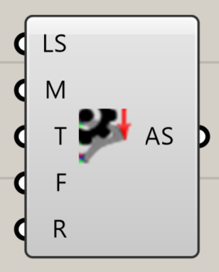
Advanced settings
Advanced settings can be specified in a separate Advanced Settings block.
Level Set Cell Size (S): Controls resolution of level set
Move Limit (M): Controls the change per iteration
Smoothing Iterations (T): Number of smoothing iterations
Fix Thickness (F): Width of region around boundary condition to remain unchanged
Retain Interfaces (R): Preserves the interface between design and non-design components
Settings Description
Regular Settings
Setting |
Description |
Recommended |
Default |
Effect |
|---|---|---|---|---|
Volume Fraction Constraint (V) |
Sets the target volume of the final design as a fraction of the initial volume |
user-defined based on design requirements |
0.5 |
Lower values remove more material, resulting in lighter designs |
Number of design iterations (N) |
Sets the maximum number of iterations for the optimization process. |
|
|
Higher values allow for more refined designs but increase computation time. Lower values result in quicker computation, but the design may be less optimized. |
Resolution (Res) or Finite Element Cell Size (S) |
Sets the resolution of the finite element mesh used in the analysis |
user-defined based on problem complexity |
|
Higher resolution provide more accurate analysis but longer computation time. |
Starting Design Geometry (G) |
Allows users to begin optimization from an existing design or custom geometry |
user-defined |
None |
Used as a starting point to refine an existing design. |
Advanced Settings
Advanced Setting |
Description |
Recommended |
Default |
Effect |
|---|---|---|---|---|
Level Set Cell Size (LS) |
Determines the size of the level set grid cells relative to the FEA grid |
0.25 to 1.0 (fraction of FEA grid size) |
0.5 |
Smaller values create finer, more detailed features but slower convergence; larger values speed up the optimization process |
Move Limit (M) |
Controls the extent of changes per optimization iteration, as a factor of the level set cell size |
0.5 to 2.0 (factor of level set cell size) |
1.0 |
Higher values lead to faster convergence, but may be unstable; lower values provide more gradual, stable changes. |
Smoothing Iterations (T) |
Defines how often the geometry is smoothed during the optimization process |
1 to 10 (iterations), |
1 |
Frequent smoothing (lower values) results in smoother designs; less frequent smoothing preserves finer details. |
Fix Thickness (F) |
Specifies the width around load and boundary conditions that remains unchanged |
2.0 to 10.0 (factor of level set cell size) |
4 |
Preserves critical regions around loads and supports, ensuring they are not altered during optimization. |
Retain Interfaces between Components (R) |
Allows users to specify if the interface between the design domain and the non-design domain should be fully preserved |
|
|
|
Examples
Below are examples which go over the LevelOpt workflow setup, post-processing, and results.
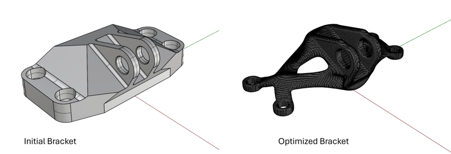
Example: GE Bracket Optimization
This demo is available for download.
GE Bracket workflow
Run an Intact stress simulation. Follow the Getting Started guide to learn how to run a stress simulation.
specify the component(s) geometry & material
reference the surfaces/meshes and specify inputs for restraints and loads
set the fidelity for the solver via the settings (resolution/cell size)
solve
(optional) visualize quantities such as displacement or von Mises stress
Specify the LevelOpt input parameters:
LevelOpt Advanced Settings block
level set cell size = 0.75
move limit = 1.0
smoothing period = 1
design domain component to optimize (from the stress simulation)
Intact stress simulation output
max iterations = 50 (1 iteration used in video starting from the final iteration for brevity)
volume fraction constraint = 0.25
Solve LevelOpt & post-process
click Solve after all inputs are connected
(optional) visualize velocities/sensitivities
(optional) bake/view final mesh in Rhino
(optional) view iteration log output to see volume fraction and compliance
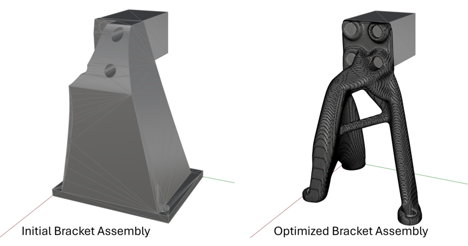
Example: NASA EXCITE Bracket Assembly
This demo is available for download.
NASA EXCITE Bracket workflow
Run an Intact stress simulation. Follow the Getting Started guide to learn how to run a stress simulation.
specify the component(s) geometry & material
reference the surfaces/meshes and specify inputs for restraints and loads
set the fidelity for the solver via the settings (resolution/cell size)
solve
(optional) visualize quantities such as displacement or von Mises stress
Specify the LevelOpt input parameters:
LevelOpt Advanced Settings block
level set cell size = 0.50
move limit = 1.0
smoothing period = 1
design domain component to optimize (from the stress simulation) note that this corresponds to the bracket geometry component, not the block component to which the load is applied
Intact stress simulation output
max iterations = 100 (1 iteration used in video starting from the final iteration for brevity)
volume fraction constraint = 0.20
Solve LevelOpt & post-process
click Solve` after all inputs are connected
(optional) visualize velocities/sensitivities
(optional) bake/view final mesh in Rhino
(optional) view iteration log output to see volume fraction and compliance