Surface Loads
Surface loads are applied to faces of the components participating in the simulation by connecting to the Loads input on the stress solver component. ⚠️ Also, refer to Using lists for Intact components for explanation of how list input works with Load Blocks.
Vector Force
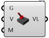
A “Vector Force” load is a surface load applied to a face in a specified direction. An example of this load is pressing on the top of a book to push it across a table.
A Vector Load requires three inputs:
the geometry of the surfaces where the load is applied
the direction of the force (a vector)
the magnitude of the force
Bearing Force
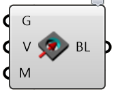
A “Bearing Load” is a surface load applied to a (typically) cylindrical face to approximate the effects of a shaft pressing against the side of a hole. The applied force gets converted to a varying pressure distribution on the portion of the face experiencing compressive pressure. The pressure distribution is computed automatically to achieve the specified overall bearing force.
A Bearing Load requires three inputs:
the geometry of the surfaces where the load is applied
the direction of the bearing force (a vector)
the magnitude of the force
Pressure
A “Pressure” load is a surface load specified in terms of force per unit area that is normal to the surface. Positive pressures push into the surface, negative pressure pull.
A Pressure Load requires two inputs:
the geometry of the surfaces where the pressure is applied
the magnitude of the pressure
Torque
A “Torque” load is a surface load that applies a twisting force around an axis. The direction of the torque is determined using the right hand rule: using your right hand, point your thumb in the direction of the axis. A positive torque value applies a torque acting in the direction the fingers of your right hand would wrap around the axis. The torque load is applied among the load faces with a distribution that varies linearly from zero at the axis.
A Torque load requires three inputs:
the geometry of the surfaces where the load is applied
the axis of the torque (a line segment)
the value of the torque

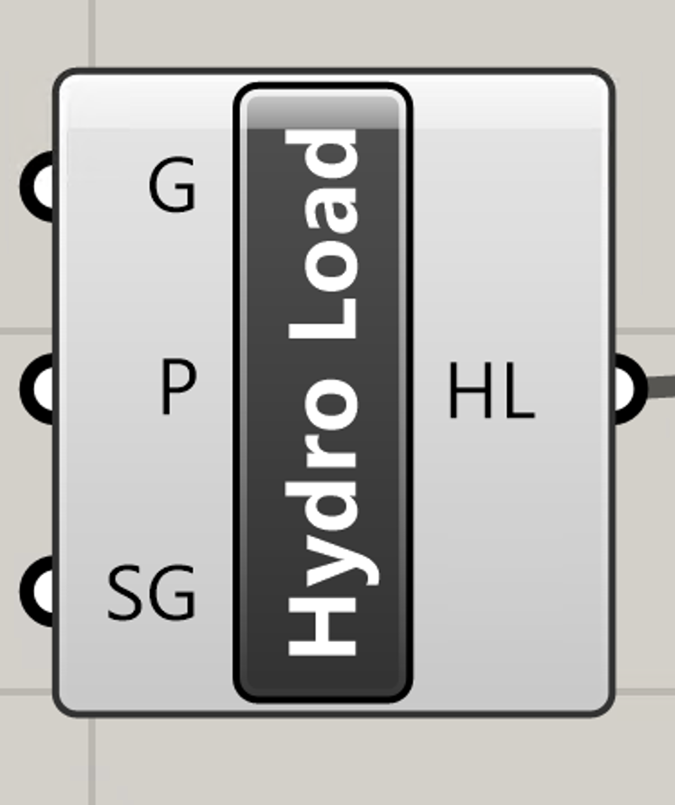
Hydrostatic Load
A “Hydrostatic” load is a spatially varying pressure as experienced by the walls of a pool due to the weight of the water pressing against them. The pressure at any point depends on the density of the water, increasing from a value of zero at the water surface to a maximum at the deepest point.
A Hydrostatic load requires three inputs:
the geometry of the surfaces where the load is applied
a point on the surface of the fluid (fluid depth is assumed in the -Z direction)
specific gravity of the fluid (dimensionless, SG = 1 for water)