Intact for nTop
Intact.Simulation offers a revolutionary meshing-free finite element method now fully integrated with nTop, enabling users to explore their design space rapidly without the usual meshing bottlenecks. This advanced technology is particularly adept at handling large geometric complexities, such as intricate lattice structures, which are often challenging to mesh using traditional finite element analysis (FEA) methods.
Key features and capabilities
Geometry Support
Implicit
Brep
Physics Support
Stress
Thermal
Modal (Coming Soon)
Quickstart with a Recorded Webinar
Watch this recorded webinar showcasing Intact.Simulation for nTop:
1. Getting Started
1.1 Installation and Accessing Intact inside nTop
Download and install Intact Simulation for nTop
You will receive download info and software license in an email.
Default Installation directory (
Intact Directory):C:\Users\$username$\AppData\Local\Programs\Intact.Simulation for nTopDocumentation and Example files are in
C:\Users\$username$\AppData\Local\Programs\Intact.Simulation for nTop\Getting Started
Move custom Intact blocks to nTop’s My Blocks folder directory
Go to:
nTop menu > File > My blocks folderCopy Intact custom blocks from
C:\Users\$username$\AppData\Local\Programs\Intact.Simulation for nTop\Custom Blocksto nTop’sMy Blocks folder.
Restart nTop. Now you can access Intact Blocks within nTop by Searching “Intact“
1.2 Example Simulations
📌 See the file Example_GyroidShear.ntop in the Getting Started folder. Update the Intact Dir and Project Dir variables.
Change the parameter Gyroid Cell Size to automatically update the simulation results.

2. How To Guide
The high-level workflow of nTop-Intact Integration. Intact requires the inputs needed for any typical structural FEA such as geometry, material, boundary conditions, and simulation settings.

Figure: Black boxes are nTop blocks. Blue boxes are Intact custom blocks
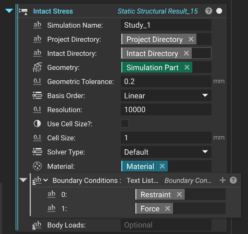
2.1 Intact Stress Custom Block
First import the Intact Stress block for directly analyzing an implicit geometry or Intact Stress (Surface Mesh) for analyzing a Brep (surface mesh) geometry.
Before setting up the simulation, set up the folders and simulation name.
Simulation Name: A name for your simulation.Project Directory: A directory to save the simulationIntact Directory: Directory where Intact Program lives. The default is in the following folder in your AppData (replace \(username\) with your user name).C:\Users\$username$\AppData\Local\Programs\Intact.Simulation for nTop
2.2 Intact Thermal Custom Block
First import the Intact Thermal block for directly analyzing an implicit geometry or Intact Thermal (Surface Mesh) for analyzing a Brep (surface mesh) geometry.
Before setting up the simulation, set up the folders and simulation name.
Simulation Name: A name for your simulation.Project Directory: A directory to save the simulationIntact Directory: Directory where Intact Program lives. The default is in the following folder in your AppData (replace \(username\) with your user name).C:\Users\$username$\AppData\Local\Programs\Intact.Simulation for nTop
2.3 Component Setup
Geometry
The simulation component consists of geometry and material.
When using the
Intact Stressblock, theGeometrymust be a nTop implicit model. Intact.Simulation can represent the implicit model as a VDB or Voxel Model: The VDB model efficiently stores the implicit field at the nodes of the voxel and interpolates the implicit field within the voxel. Voxel size is specified using theGeometry Tolerance****parameter, which can be decided based on the minimum feature size as well as the level of accuracy desired.When using the
Intact Stress (Surface Mesh)block, the Geometry must be aSurface Mesh.
Recommendation: It is generally recommended to use VDB or Voxel Model, unless the geometry is predominantly CAD-like with edges and corners, in which case surface tessellation could be faster.
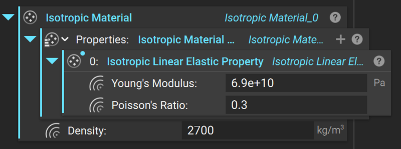
Material
Material is defined using nTop’s Isotropic Material block with Isotropic Linear Elastic Properties.
2.4 Boundary Conditions (Stress)
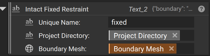
Restraints
Intact Fixed Restraint
A “Fixed Boundary” restraint fixes the selected geometry in all directions. The fixed boundary only has one input:
Unique NameProject DirectoryBoundary Meshsurface to be fixed (must be a surface mesh)
Intact Displacement Restraint
A “Fixed Vector” restraint allows for each direction to be optionally set to a specified displacement value, 0 being fixed and ‘None’ being un-restrained. Note that a structural problem must have all three directions restrained somewhere to be valid. Also, note that this boundary condition doesn’t take custom units and it’s always in the units of the scenario metadata.
A fixed vector requires the following inputs:
Unique NameProject Directorythe
Mesh Boundarysurface to be fixedthe
*_Displacementmagnitude with distance units to set the displacement for the *-axis direction (ignored if the toggle is off)
In the example below, the Z-axis is considered “free” and thus the z-displacement value is ignored/replaced by ‘null’ regardless of its input.

Structural Loads
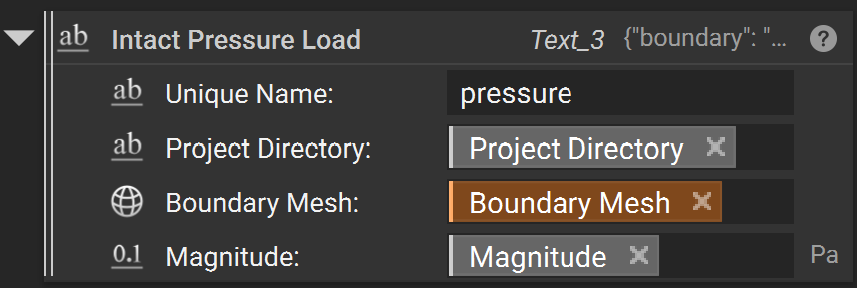
Pressure
A “Pressure” load is a surface load specified in terms of force per unit area. Positive pressures ‘push’ into the surface, and negative pressures ‘pull’.
A Pressure Load requires three inputs:
Unique NameProject Directorythe
boundarysurfaces where the load is appliedthe
UnitSystemthat applies to the magnitude - needs to be specified before the magnitude is set (default MKS)the
Magnitudeof the pressure with units (e.g. ‘Pa’ for Pascal).
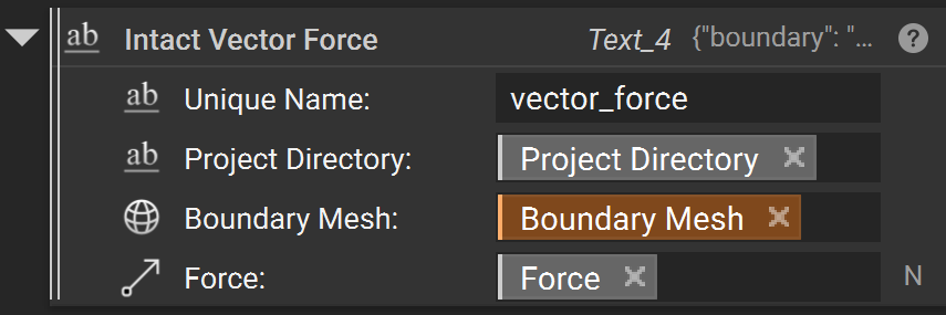
Vector Force
“Vector Force” load is a surface load applied to a face in a specified direction. An example of this load is pressing on the top of a book to push it across a table.
A vector load requires four inputs:
Unique NameProject Directorythe
Boundary Meshsurfaces where the load is appliedthe
Forcevector with force units (e.g. ‘N’ for Newton)
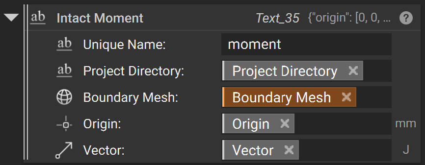
Moment Load
“Moment” load is a surface load that applies a twisting force around an axis. The direction of the moment is determined using the right-hand rule: using your right hand, point your thumb in the direction of the axis. A positive moment value applies a moment acting in the direction the fingers of your right hand would wrap around the axis. The moment load is applied among the load faces with a distribution that varies linearly from zero at the axis.
A Moment load requires five inputs:
Unique NameProject Directorythe
Boundary Meshsurfaces where the load is appliedOriginis the starting point of the axis of rotationthe
Vectorwhich species the axis of rotation and the magnitude with units (e.g. ‘N*m’ for Newton-Meter).
Bearing Force
A “Bearing Force” is a surface load applied to a (typically) cylindrical face to approximate the effects of a shaft pressing against the side of a hole. The applied force gets converted to a varying pressure distribution on the portion of the face experiencing compressive pressure. The pressure distribution is computed automatically to achieve the specified overall bearing force.
A Bearing Force requires three inputs:
Unique NameProject Directorythe
Boundary Meshsurfaces where the load is appliedthe
Direction Vectorof the bearing forcethe
Magnitudeof the load with force units (e.g. ‘N’ for Newton)

Body Loads
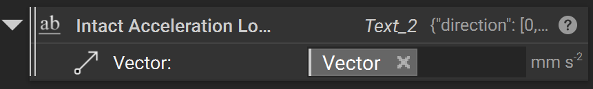
Acceleration Body Load
An “Acceleration Body Load” is a linear acceleration body load that acts on the entire component/body.
An Acceleration Body Load requires a single input:
the
Vectorof the acceleration which describes both the direction and magnitude of acceleration with units (e.g. ‘m/s^2’)
Rotational Body Load
A “Rotational Body Load” is a rotational body load that acts about a prescribed axis on an entire component/body.
A Rotational Body Load requires four inputs:
the
Origin of Rotation Axisabout which the rotational body load acts.the
Direction of Rotation Axiswhich describes the direction of the axis about which the rotational body load acts.the
Angular Velocityof the rotational body load with units (e.g. ‘rad/s’)the
Angular Accelerationof the rotational body load with units (e.g. \(rad / s^2\))

2.5 Boundary Conditions (Thermal)
Restraints
Temperature Restraint (Fixed Temperature)
A “Temperature Restraint” restraint fixes the temperature of a selected geometry to a set value. The fixed boundary custom block has four inputs:
Unique NameProject DirectoryBoundary Meshsurface to be fixed (must be a surface mesh)Temperature

Thermal Loads
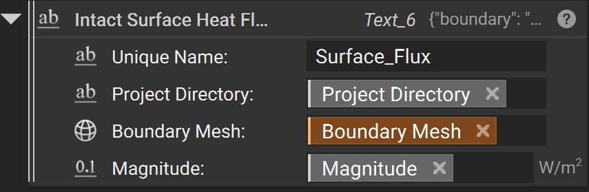
Surface Flux
A “Surface Flux” load is a surface load specified in terms of power per unit area.
A Surface Flux Load block requires four inputs:
Unique NameProject Directorythe
Boundary Meshsurfaces where the load is appliedthe
Magnitudeof the flux with units (e.g. ‘W/m^2’)
Convection
A “Convection” load specifies the transfer of heat from a surrounding medium.
A convection load requires five inputs:
Unique NameProject Directorythe
Boundary Meshsurfaces where the load is appliedthe
Heat Transfer Coefficientwith units (e.g. ‘W/m^2)the
Ambient Temperatureof the medium with units of temperature (e.g. ‘K’)

Thermal Body Loads
Volumetric Heat Generation
A “volumetric heat generation” load is a flux body load which applies uniform heat generation all over the component (volume).
Volumetric heat generation requires a single input:
the
Magnitudeof the flux with units (e.g. ‘W/m^3’)

2.6 Simulation Settings
Intact.Simulation allows customizations to support rapid coarse as well as accurate fine simulation as desired. The following Simulation Settings are available:
The
Basis orderis the order of finite elements used. It can beLinear(default) orQuadratic.Note that with quadratic elements, far fewer elements are needed to compute an accurate solution. However, quadratic elements are much more expensive in terms of time and memory resources than linear elements.
Recommendation:
Quadratic elements are suited for bending dominant problems like thin shells and beam-type structures.
Specify Precision Type and Precision Value for the desired accuracy/speed of the simulation.
Resolutionis the target number of finite elements. An iterative process determines aCell sizethat achieves approximately the specified number of elements. The simulation log in the Project directory contains the exact cell size and number of finite elements used in the simulation.You can toggle on
Use Cell Size?to directly specify theCell Sizeinstead of theResolution, for example, when you want to resolve the correct behavior of certain geometric features. Note that whenUse Cell Size?isOn,Resolutionis ignored.The immerse grid for the simulation is stored in
_solution.vtuin the project folder and can be visualized if desired (using Paraview).Recommendation:
We recommend using
Resolutionif you are unsure of the cell size. A smallCell Sizecan quickly result in a large number of finite elements and long solve times.
Solver Typeis the linear solver used in the simulation with the following options:Direct“directly” solves the linear system and is very robust but typically consumes more memory, which can be a problem for high resolution or small cell size.Iterativesolves the linear system “iteratively” and uses less memory thanDirect. They are suited for high resolutions.Default: Sets the solver automatically based onBasis orderandResolution.For static structural
Linearelements, default isIterativeSolver for resolution greater than 200K andDirectSolver for less than 200K. Note that if thePrecision Typeiscell size, the default is alwaysIterativefor linear elements.Quadraticelements, it defaults toDirectsolver for all resolutions or cell sizes.Thermal solvers default to
Direct, if desiredIterativecan be manually selected for some cases which utilize large amounts of memory.
2.7 Result Visualization
Default Result Visualization
By default, the visualization produced by the Intact Stress block includes both Displacement and von Mises stress fields. These can be accessed like other simulation results in nTop. Currently, visualization is supported only on surface tessellation, even for implicit geometry (visualization directly on implicit is in work in progress). The default surface meshes for different geometric representations are as follows:
Implicit/Voxel Model: Intact produces visualization on a surface mesh that represents the zero-level set as approximated by the voxel grid. You can also resample the solution on a higher-quality surface mesh for improved visualization.
Brep (Surface Mesh): Visualization is done on the input surface mesh geometry.

Resampling Immerse Grid Solution
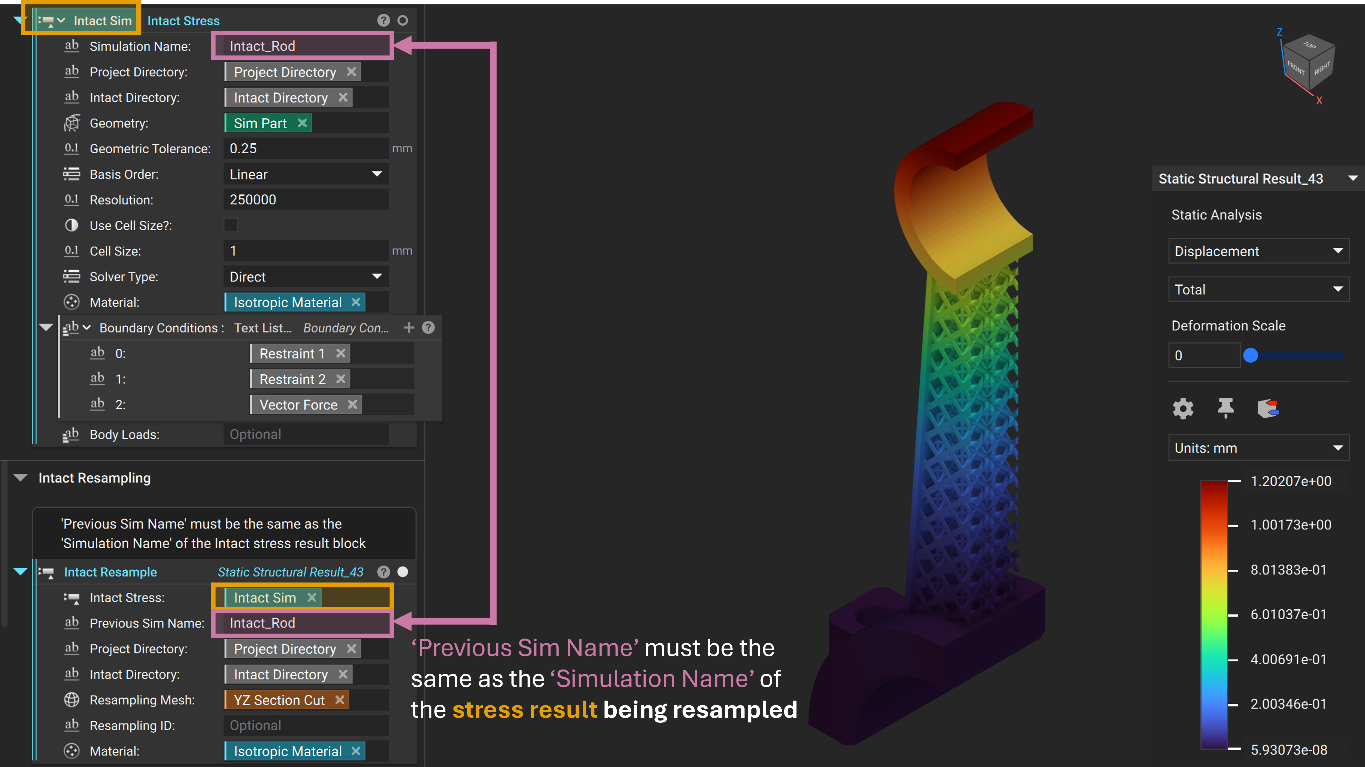
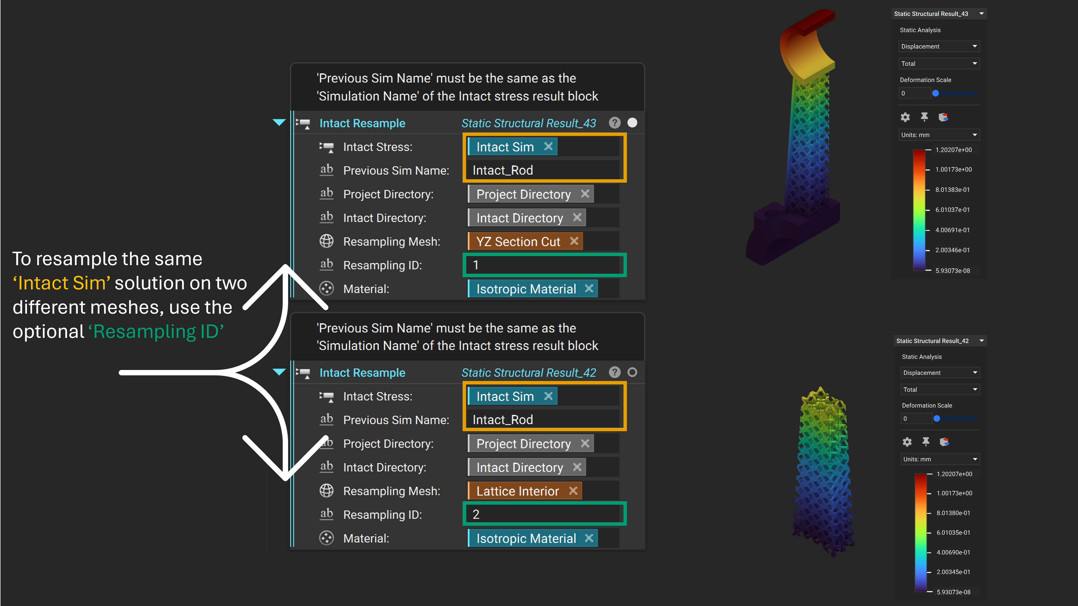
The solution is computed on an immersed grid and can be interpolated within the grid cells. To resample an existing solution, use the Intact Resample block**.** Resampling can generate a better visualization or create slice/cross-section views.
Intact Stressis theIntact Stresssimulation being resampledPrevious Sim Name: The name of theIntact Stresssimulation being resampledProject DirectoryIntact DirectoryResampling Mesh: The new mesh for resampling the FEA solution for visualizationResampling ID: An optional input which allows resampling the sameIntact Stresssimulation on multipleResample MeshesMaterial: The material used for computing stresses (Should be the same as theIntact Stresssimulation being resampled)
📌 For a resampling example see the file Example_StaticConnectingRod.ntop in the Getting Started\Static Structural folder. Update the Intact Directory/Project Directory variables and manually run the unloaded lattice block to generate the geometry.
3. Technology Overview
3.1 Immersed Method of Moments Overview
Immersed Method of Moments (IMM) is a technology that uses the Finite Element Analysis (FEA) for performing simulation tasks, without the need to build a conformal mesh. IMM adopts an immersed-grid methodology where the geometry is “immersed” in a non-conformal background grid; and our patent-pending moment-vector technology is used to compute geometry and material-dependent quantities (e.g., element quadrature) at runtime for the FEA.
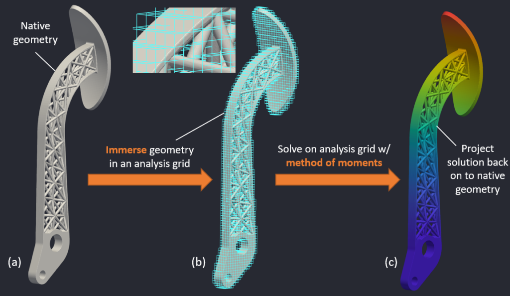
Figure: Immersed method of moments: Geometry is immersed in a grid & solved using the method of moments.
The above picture captures the essence of IMM. The geometry (left image) is immersed in a background analysis grid (middle image). The elements in the analysis grid are conventional FEA elements (e.g., 8-noded hexahedral linear elements or 27-noded hexahedral quadratic elements), except that the quadrature used for the elements are computed using the method of moments. For instance, an element that is completely inside the the geometry will have quadrature that is different from an element that is only partially inside the geometry. After computing the solution on the analysis grid, the quantities of interest are projected back on to the native geometry (right figure).
3.2 Benchmarks
Complex Benchmark- Lightweight Piston Connecting Rod
This comparison is for a complex geometry with a lattice. The goal is to compare the displacement and stress results for a similar number of elements. The stresses are compared away from stress singularity as stresses in areas of stress concentration do not converge.
📌 See the file Example_StaticConnectingRod.ntop in the Getting Started\Static Structural folder. Update the Intact Directory/Project Directory variables and manually run the unloaded lattice block to generate the geometry.
Number of Elements |
Displacement (mm) |
Total Time (secs) |
|
|---|---|---|---|
nTop mesh-based FEA |
330,000 |
1.18 |
215 (includes meshing) |
Intact IMM FEA |
300,000 |
1.20 |
229 (includes VDB export) |
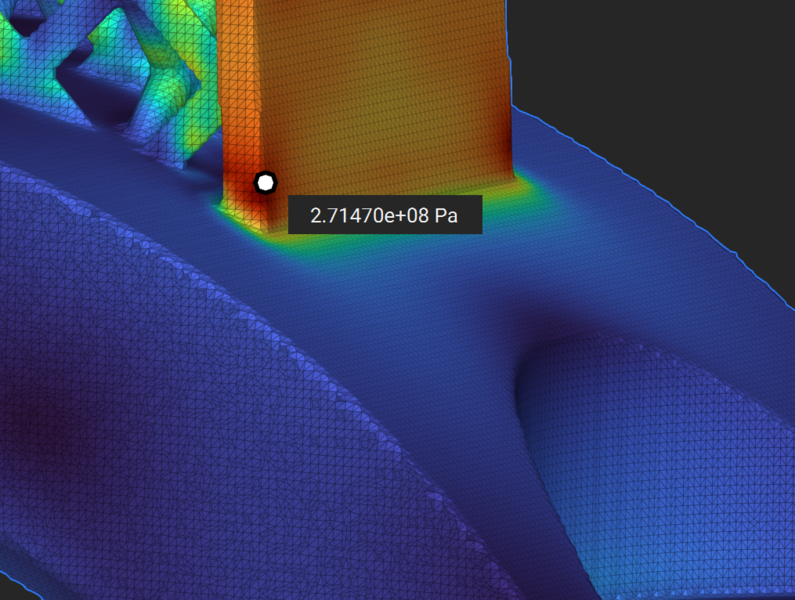
von Mises Stress comparison


Standard Benchmark- Beam
📌 See the file Benchmark_PlateWHole.ntop in the Getting Started\Static Structural folder. Update the Intact Directory/Project Directory variables and manually run any necessary unloaded blocks.
Displacement from Intact IMM vs nTop mesh-based FEA
Analytical |
nTop mesh-based FEA |
Intact IMM FEA |
|
|---|---|---|---|
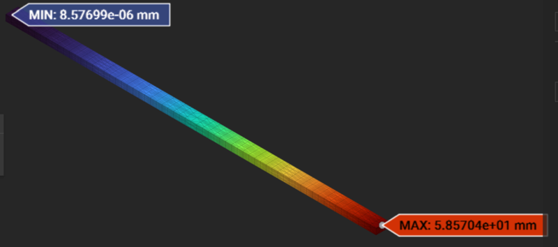
Beam Bending |
59.19 mm |
58.98 mm |
58.57 mm |
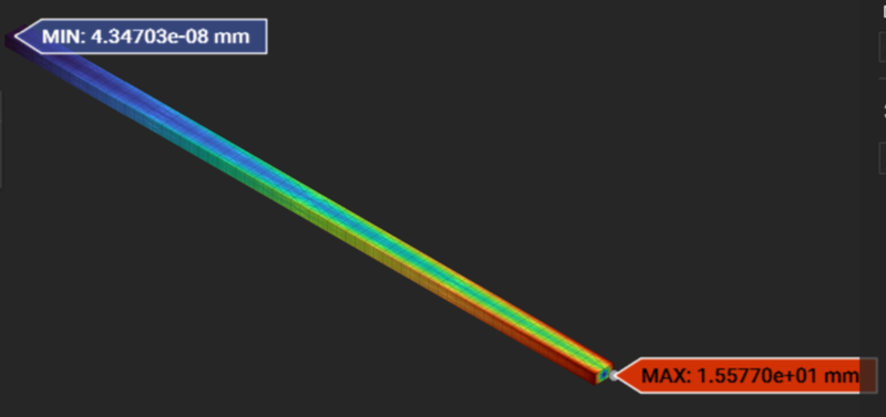
Beam Twisting |
- |
15.78 mm |
15.77 mm |
Beam Bending - nTop mesh-based:

Beam Bending - Intact:
Beam Twisting - nTop mesh-based:

Beam Twisting - Intact:
Standard Benchmark- Plate with a Hole
📌 See the file Benchmark_PlateWHole.ntop in the Getting Started\Static Structural folder. Update the Intact Directory/Project Directory variables and manually run any necessary unloaded blocks.
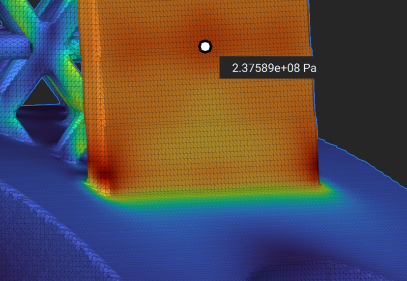
The figure below compares stress concentration due to the hole in a plate as obtained from mesh-based FEA and Intact IMM FEA.

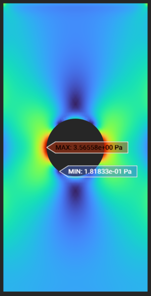
The theoretical stress concentration (Stress XX) value can be computed using the analytical formulation for the stress concentration factor given as (d is hole diameter and W is plate width)
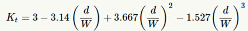
The above formula leads to a Kt = 2.233 and the resulting theoretical stress concentration value 3.72 Pa .
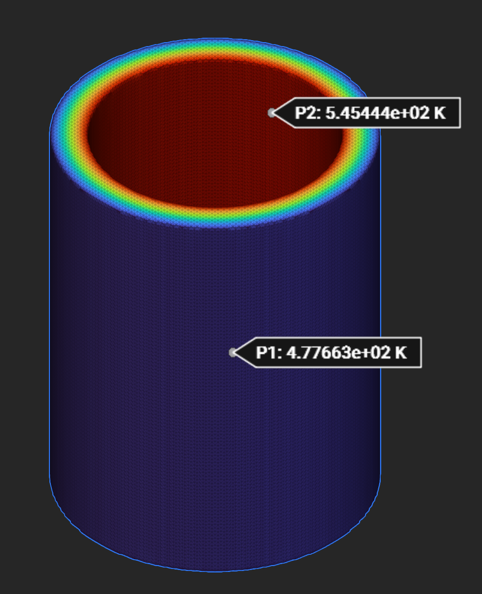
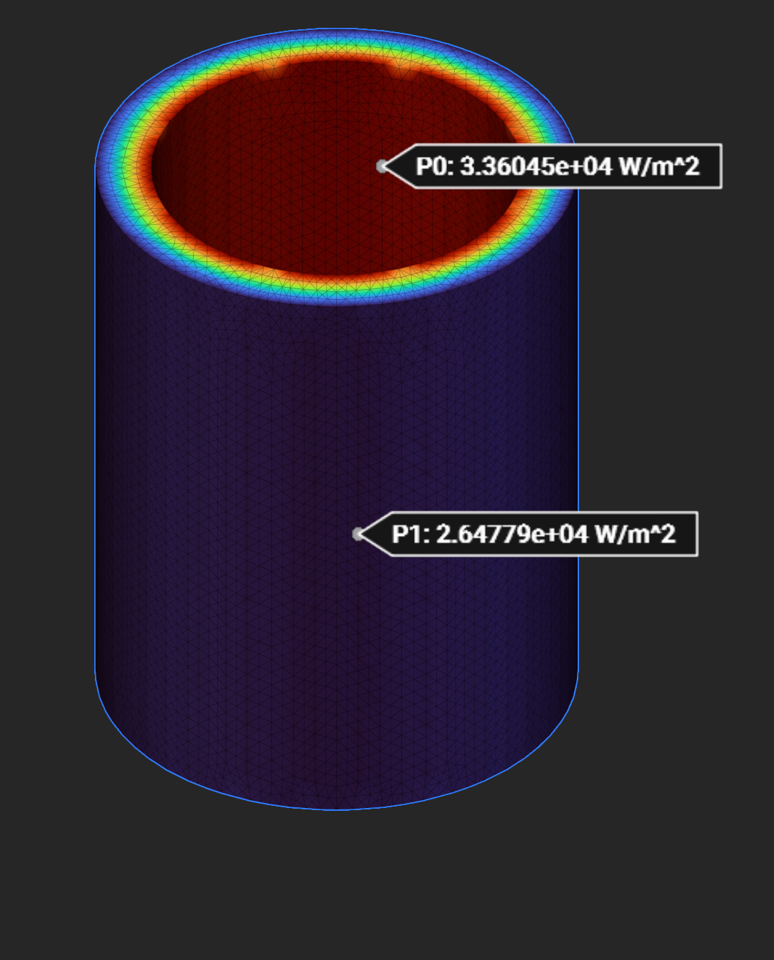
Standard Thermal Benchmark - Cylinder with Convection
📌 See the file Benchmark_ThermalCylinder.ntop in the Getting Started\Thermal folder. Update the Intact Directory/Project Directory variables and manually run any necessary unloaded blocks.
Reference* |
nTop mesh-based FEA |
Intact IMM FEA |
|
|---|---|---|---|
Inner Temperature (K) |
545.45 |
545.36 |
545.44 |
Outer Temperature (K) |
478.25 |
477.96 |
477.66 |
Inner Convection (W/m^2) |
34,160 |
33,294 |
33,605 |
Outer Convection (W/m^2) |
26,280 |
27,164 |
26,478 |
*Societe Francaise des Mecaniciens. Guide de validation des progiciels de calcul de structures. Paris, Afnor Technique, 1990. Test No. TPLA03/89.
Temperature - nTop mesh-based:

Temperaure - Intact:
Heat Flux - nTop mesh-based:
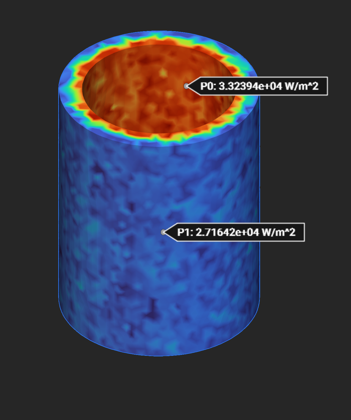
Heat Flux - Intact:
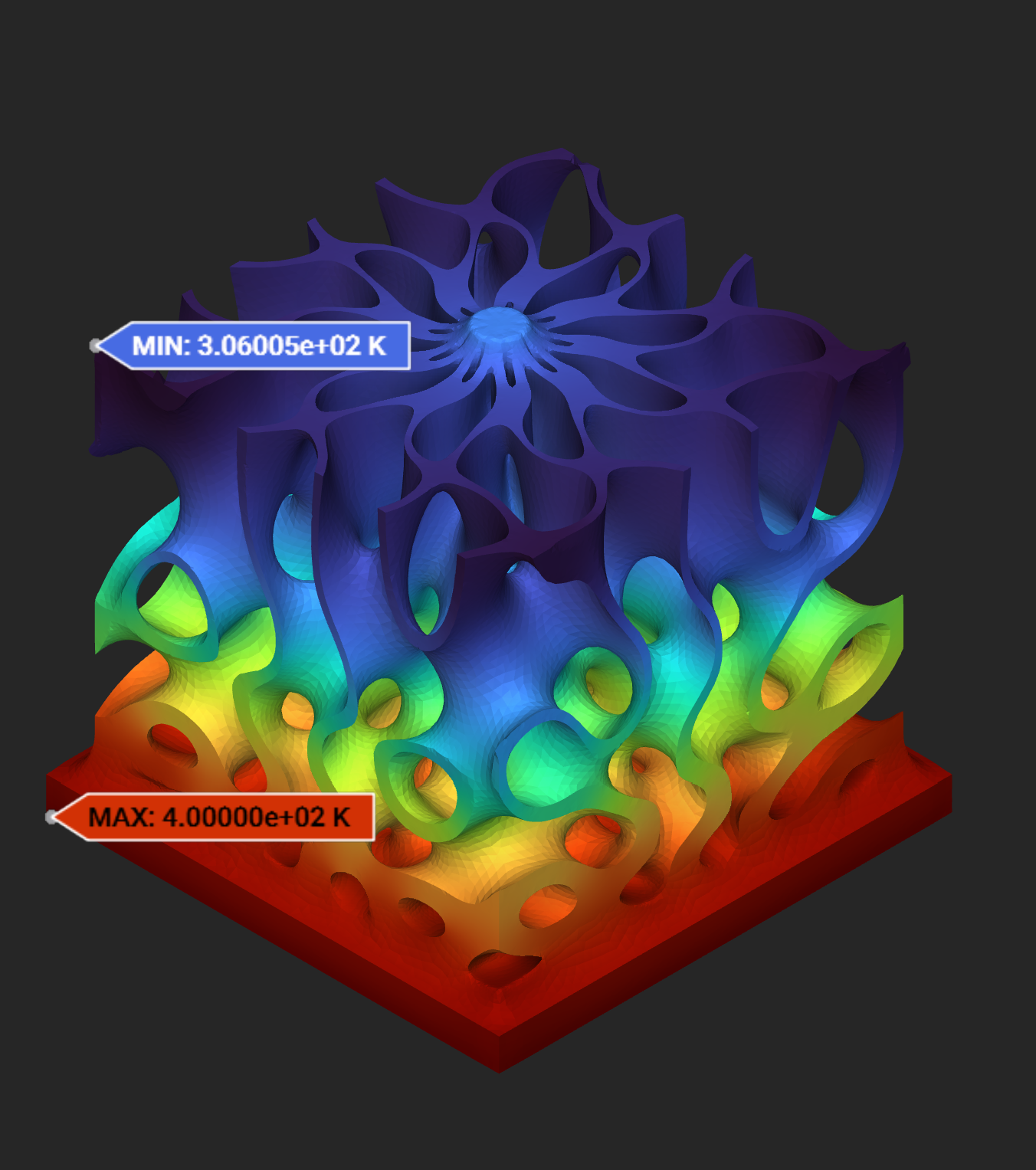
Complex Thermal Benchmark - Gyroid Heat Sink
📌 See the file Example_ThermalHeatSink.ntop in the Getting Started\Thermal folder. Update the Intact Directory/Project Directory variables and manually run any necessary unloaded blocks.
# of Elements |
Max/Min Temp (K) |
Total Time (secs) |
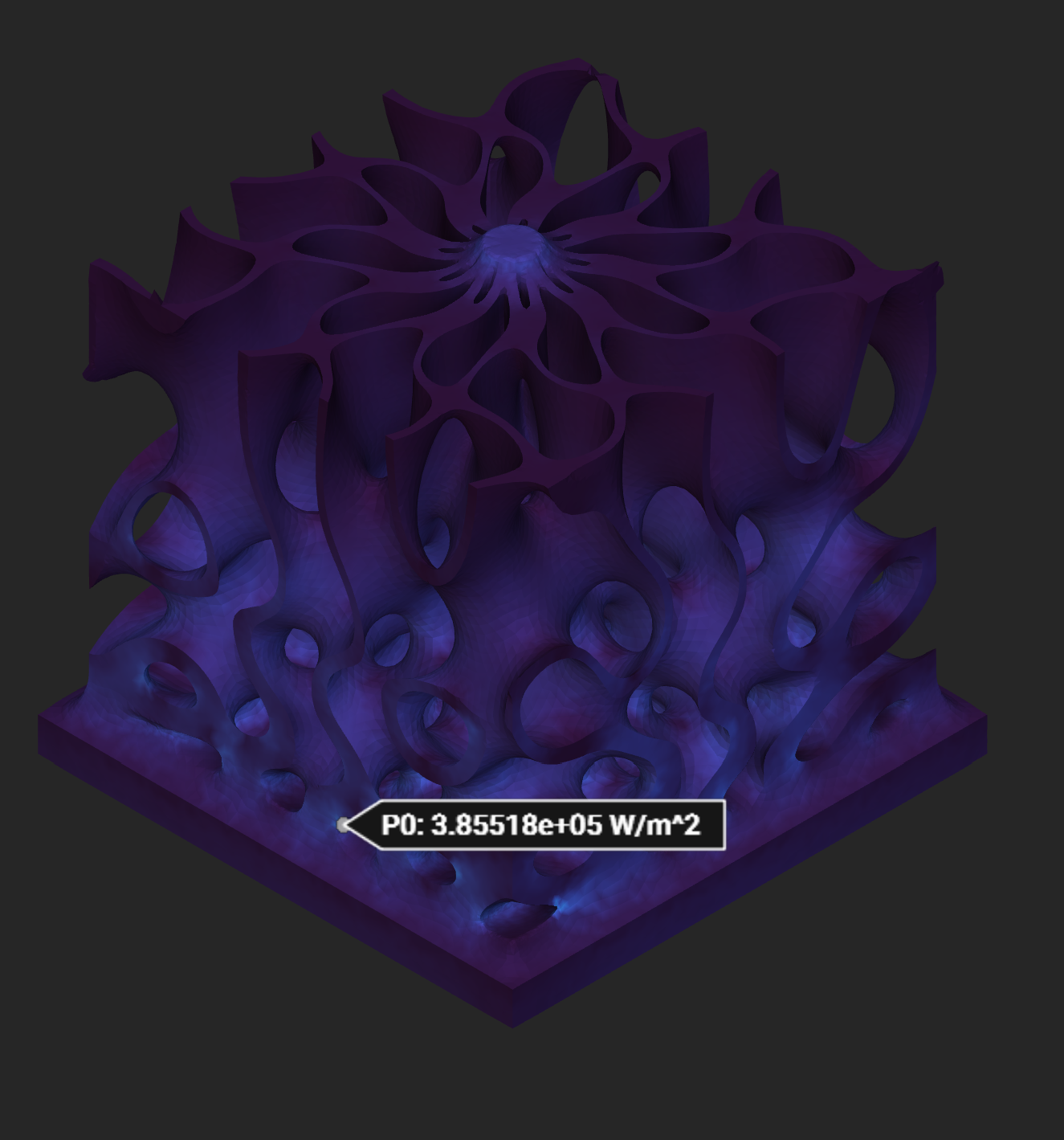
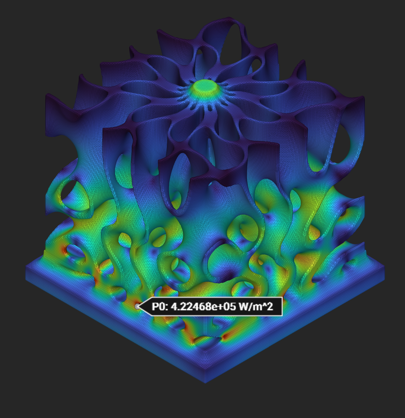
Local Flux (W/m^2) |
|
|---|---|---|---|---|
nTop mesh-based FEA |
293,625 |
400/306 |
215 (includes meshing) |
3.86e5 |
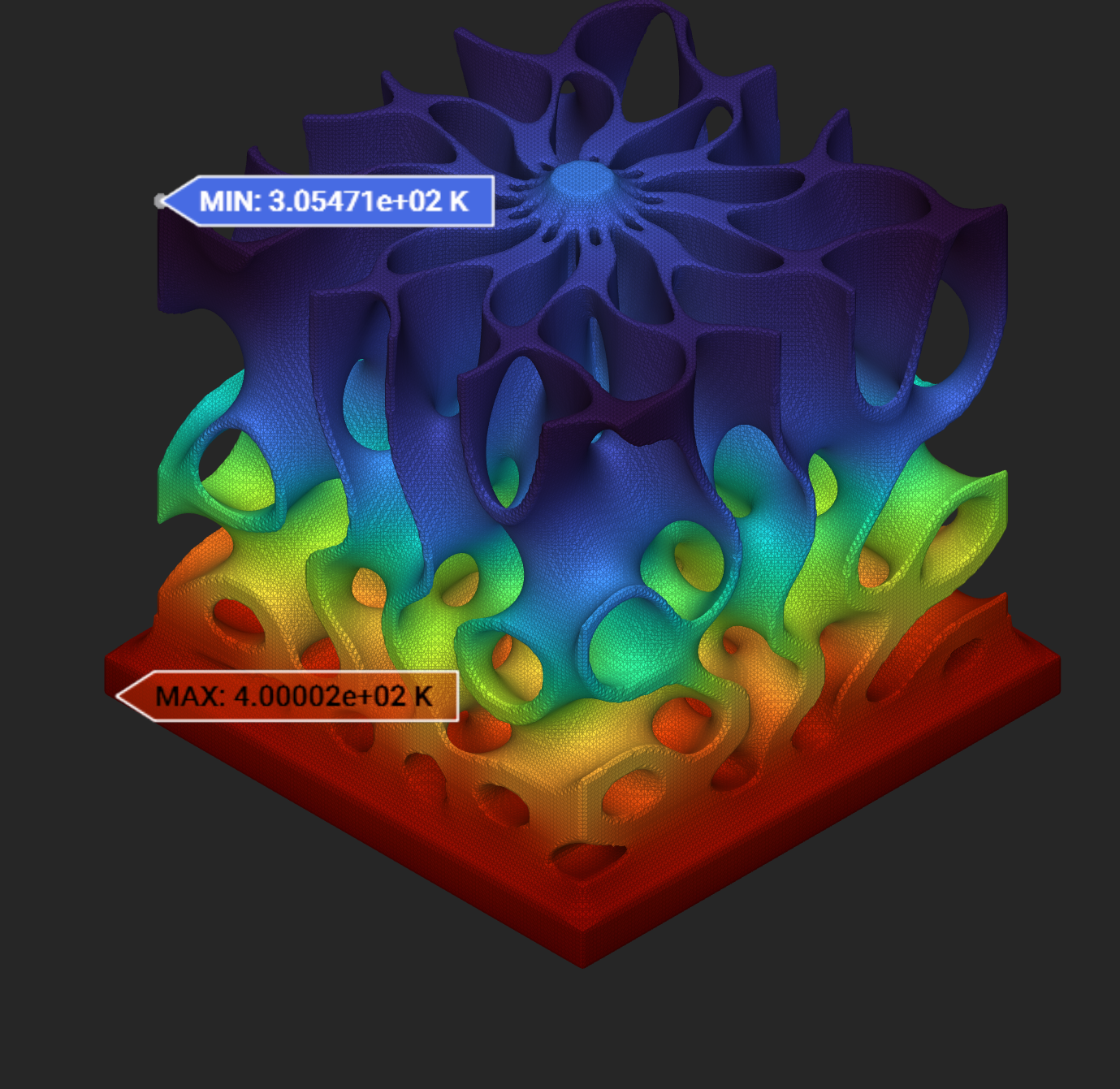
Intact IMM FEA |
312,831 |
400/305 |
76 |
4.22e5 |
nTop Temperature:
Intact Temperature:
nTop Heat Flux (note there is some global maxima which impacts the flux scale):
Intact Heat Flux:
Release notes
[1.0.2] - 2024-10-10
Made
intact_ntopa self-contained executable, so it is no longer necessary to separately install the .NET runtime.The resampling custom block now allows resampling the a solution multiple times when provided an optional “Resampling ID”.
Fixed a bug so the sample geometry is written to the project directory, and not the installation directory.
[1.0.0] - 2024-10-1
Initial release of Intact.Simulation for nTop.