Connector Blocks
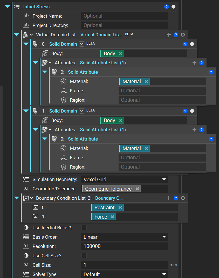
Intact Stress Block
This block has the following inputs:
(optional)
Project Name: A unique simulation name to store multiple runs in the same directory for additional post-processing or resampling.(optional)
Project Directory: A directory to save the simulation files to for additional post-processing or resampling.Virtual Domain List: Accepts a list of Solid Domain blocks using the implicit body overload.Simulation Geometry: Specifies the type of geometry used in simulation, takes: voxel grid, surface mesh, or direct on implicit.Geometric Tolerance: The fidelity used forSimulation Geometry, voxel size or mesh tolerance.Boundary Condition List: Accepts a list of nTop boundary conditions using eitherCAD Face overload
Boundary overload using an implicit input via
Virtual Boundary by Body
Use Inertial Relief?: Boolean toggle to use inertial relief in absence of sufficient FE contraints.Basis Order: Selection of linear or quadratic order for the finite element analysis.Resolution: Simulation fidelity, approximate number of elements to use.Use Cell Size?: Boolean toggle to use cell size directly instead of resolution.Cell Size: Simulation fidelity, edge length of each elementSolver Type: Selection of default, direct, or iterative solver.
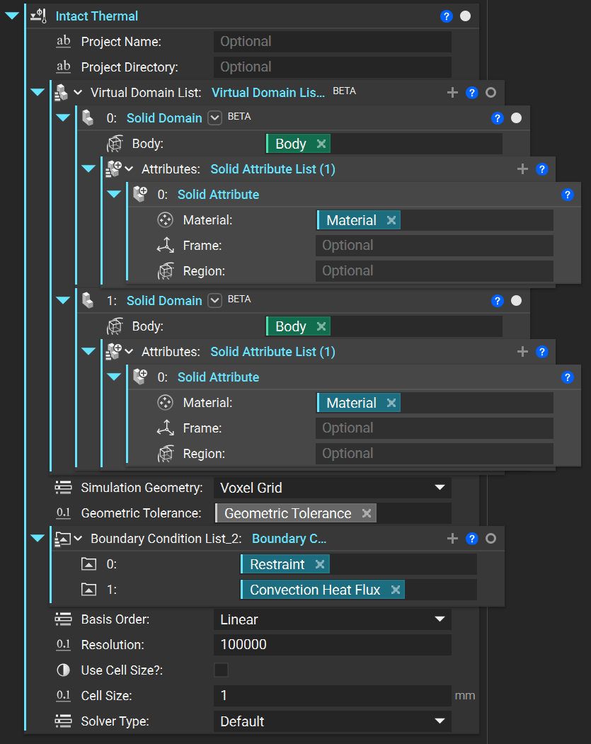
Intact Thermal Block
This block has the following inputs:
(optional)
Project Name: A unique simulation name to store multiple runs in the same directory for additional post-processing or resampling.(optional)
Project Directory: A directory to save the simulation files to for additional post-processing or resampling.Virtual Domain List: Accepts a list of Solid Domain blocks using the implicit body overload.Simulation Geometry: Specifies the type of geometry used in simulation, takes: voxel grid, surface mesh, or direct on implicit.Geometric Tolerance: The fidelity used forSimulation Geometry, voxel size or mesh tolerance.Boundary Condition List: Accepts a list of nTop boundary conditions using eitherCAD Face overload
Boundary overload using an implicit input via
Virtual Boundary by Body
Basis Order: Selection of linear or quadratic order for the finite element analysis.Resolution: Simulation fidelity, approximate number of elements to use.Use Cell Size?: Boolean toggle to use cell size directly instead of resolution.Cell Size: Simulation fidelity, edge length of each elementSolver Type: Selection of default, direct, or iterative solver.
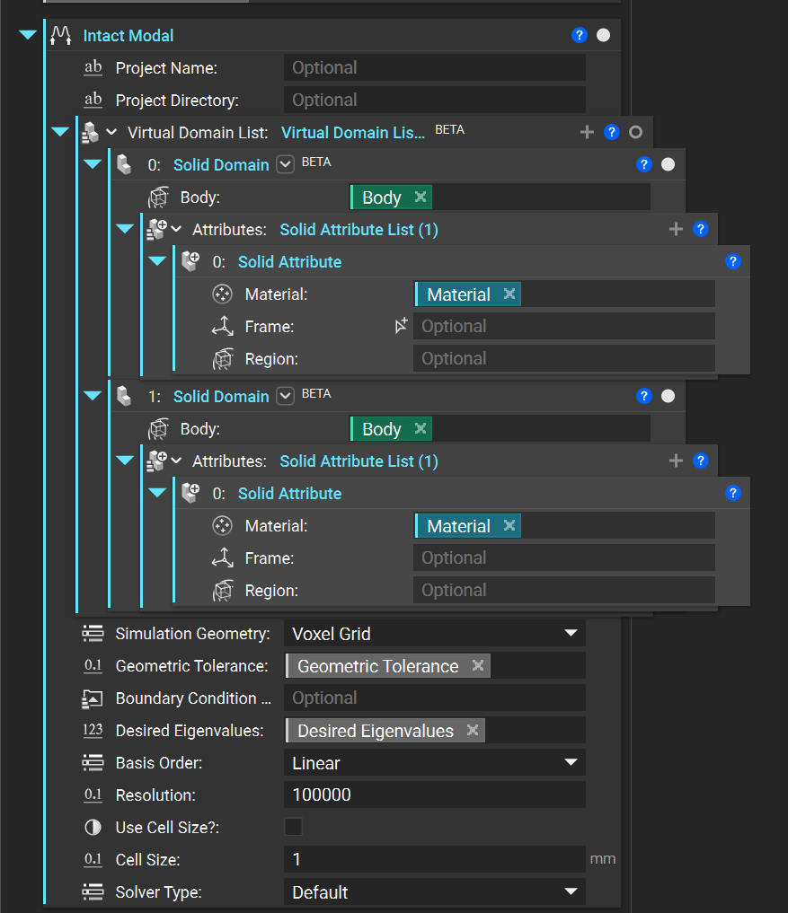
Intact Modal Block
This block has the following inputs:
(optional)
Project Name: A unique simulation name to store multiple runs in the same directory for additional post-processing or resampling.(optional)
Project Directory: A directory to save the simulation files to for additional post-processing or resampling.Virtual Domain List: Accepts a list of Solid Domain blocks using the implicit body overload.Simulation Geometry: Specifies the type of geometry used in simulation, takes: voxel grid, surface mesh, or direct on implicit.Geometric Tolerance: The fidelity used forSimulation Geometry, voxel size or mesh tolerance.(optional)
Boundary Condition List: Accepts a list of nTop boundary conditions using eitherCAD Face overload
Boundary overload using an implicit input via
Virtual Boundary by Body
Desired Eigenvalues: Specifies the number of eigenvalues to solve for.Basis Order: Selection of linear or quadratic order for the finite element analysis.Resolution: Simulation fidelity, approximate number of elements to use.Use Cell Size?: Boolean toggle to use cell size directly instead of resolution.Cell Size: Simulation fidelity, edge length of each elementSolver Type: Selection of default, direct, or iterative solver.
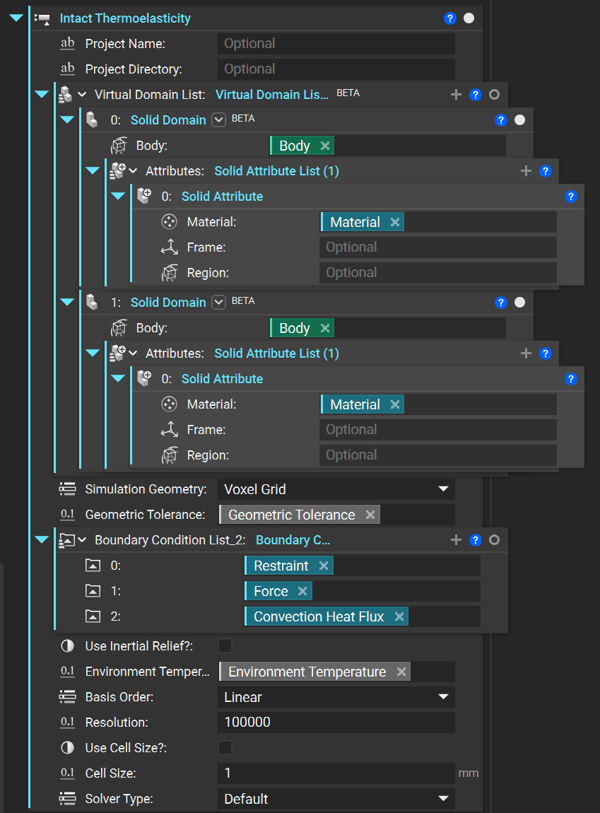
Intact Thermoelastic
This block has the following inputs:
(optional)
Project Name: A unique simulation name to store multiple runs in the same directory for additional post-processing or resampling.(optional)
Project Directory: A directory to save the simulation files to for additional post-processing or resampling.Virtual Domain List: Accepts a list of Solid Domain blocks using the implicit body overload.Simulation Geometry: Specifies the type of geometry used in simulation, takes: voxel grid, surface mesh, or direct on implicit.Geometric Tolerance: The fidelity used forSimulation Geometry, voxel size or mesh tolerance.Boundary Condition List: Accepts a list of nTop boundary conditions (linear elastic and thermal) using eitherCAD Face overload
Boundary overload using an implicit input via
Virtual Boundary by Body
Use Inertial Relief?: Boolean toggle to use inertial relief in absence of sufficient FE contraints.Basis Order: Selection of linear or quadratic order for the finite element analysis.Resolution: Simulation fidelity, approximate number of elements to use.Use Cell Size?: Boolean toggle to use cell size directly instead of resolution.Cell Size: Simulation fidelity, edge length of each elementSolver Type: Selection of default, direct, or iterative solver.
Intact Resample
This block has the following inputs:
Intact Result: TheIntact Stress,Intact Thermal,Intact Modal, orIntact Thermoelasticblock to be resampled(optional)
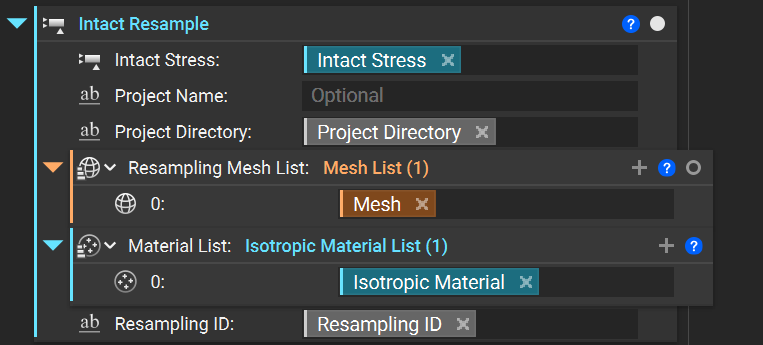
Project Name: The sameProject Nameoptionally used in theIntact Stressblock.Project Directory: The sameProject Directoryfiles were optionally stored in withIntact ResultResampling Mesh List: A list of meshes to visualize/sample the solution onto.Material List: A list of materials used for each mesh (should be the same as inIntact Result). Note these lists must be the same lengthResampling ID: Unique file identifier (for multiple resampling instances of the sameIntact Result)
Intact Sample Points
This block has the following inputs:
Intact Result: TheIntact Stress,Intact Thermal,Intact Modal, orIntact Thermoelasticblock to be resampled(optional)
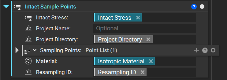
Project Name: The sameProject Nameoptionally used in theIntact Resultblock.Project Directory: The sameProject Directoryfiles were optionally stored in withIntact ResultSampling Points: A list of points to visualize/sample the solution onto.Material: A material used for sampling the points (should be the same as inIntact Result).Resampling ID: Unique file identifier (for multiple resampling instances of the sameIntact Result)
Intact Preview
This block creates a point list that is used to preview where the immersed grid is and where boundary conditions and internal conditions are applied. This block has the following inputs:
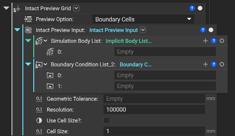
Simulation Body List: Accepts a list of implicit bodies which indicate the simulation components/domain.Geometric Tolerance: The fidelity used forSimulation Geometry, voxel size or mesh tolerance.Boundary Condition List (Optional): Accepts a list of nTop boundary conditions (linear elastic and thermal) using eitherCAD Face overload
Boundary overload using an implicit input via
Virtual Boundary by Body
Resolution: Simulation fidelity, approximate number of elements to use.Use Cell Size?: Boolean toggle to use cell size directly instead of resolution.Cell Size: Simulation fidelity, edge length of each element
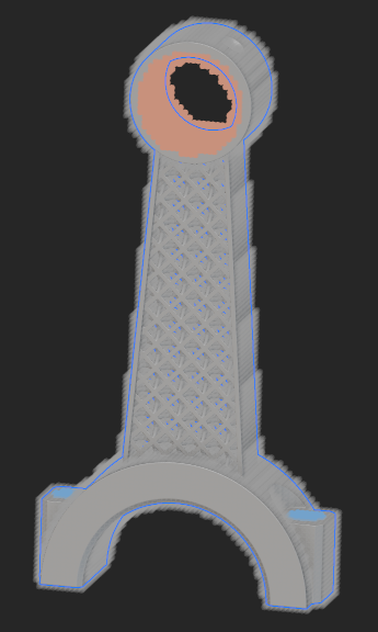
By selecting a Preview Option, you can preview the simulation setup. In the following image,
a connecting rod will be simulated, and where the restraints will be applied is denoted by the blue region
and where the loads will be applied is denoted by the orange region.
Block Inputs
Domain
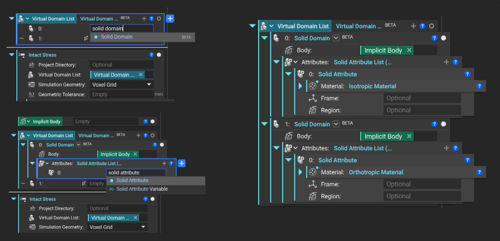
The Virtual Domain List input takes a list of virtual domains consisting of a Solid Domain block, which also contains a Solid Attribute block carrying the material properties.
Boundary Conditions
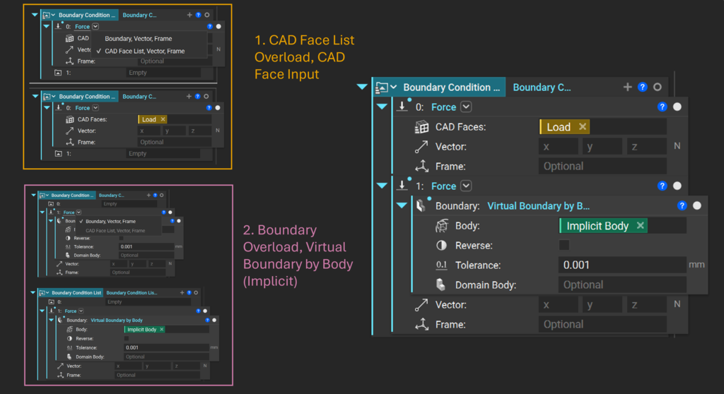
The Boundary Condition List input uses default ntop boundary condition blocks with either a CAD Face List overload or a virtual boundary by body.
Selection Region / Mask on Implicit Boundary Conditions
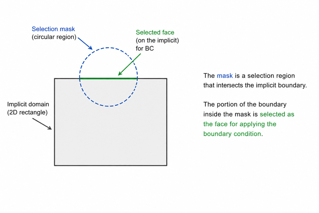
In nTop, since we’re working with implicit geometry, there isn’t an explicit notion of discrete “faces” that you can select like in CAD/B-rep models. The boundary is defined implicitly, so we need a way to localize where to apply conditions.
The “mask” is just a selection region in space. We intersect that region with the implicit boundary, and the portion of the boundary inside the mask becomes the face where the BC is applied. See the figure below for a 2D example.
Simulation Settings
Intact.Simulation allows customizations to support rapid coarse as well as accurate fine simulation as desired. The following Simulation Settings are available:
The
Basis orderis the order of finite elements used. It can beLinear(default) orQuadratic.Note that with quadratic elements, far fewer elements are needed to compute an accurate solution. However, quadratic elements are much more expensive in terms of time and memory resources than linear elements.
Recommendation:
Quadratic elements are suited for bending dominant problems like thin shells and beam-type structures.
Specify Precision Type and Precision Value for the desired accuracy/speed of the simulation.
Resolutionis the target number of finite elements. An iterative process determines aCell sizethat achieves approximately the specified number of elements. The simulation log in the Project directory contains the exact cell size and number of finite elements used in the simulation.You can toggle on
Use Cell Size?to directly specify theCell Sizeinstead of theResolution, for example, when you want to resolve the correct behavior of certain geometric features. Note that whenUse Cell Size?isOn,Resolutionis ignored.The immersed grid for the simulation is stored in
_solution.vtuin the project folder and can be visualized if desired (using Paraview).Recommendation:
We recommend using
Resolutionif you are unsure of the cell size. A smallCell Sizecan quickly result in a large number of finite elements and long solve times.
Solver Typeis the linear solver used in the simulation with the following options:Direct“directly” solves the linear system and is very robust but typically consumes more memory, which can be a problem for high resolution or small cell size.Iterativesolves the linear system “iteratively” and uses less memory thanDirect. They are suited for high resolutions.Default: Sets the solver automatically based onBasis orderandResolution.For static structural
Linearelements, default isIterativeSolver for resolution greater than 200K andDirectSolver for less than 200K. Note that if thePrecision Typeiscell size, the default is alwaysIterativefor linear elements.Quadraticelements, it defaults toDirectsolver for all resolutions or cell sizes.Thermal solvers default to
Direct, if desiredIterativecan be manually selected for some cases which utilize large amounts of memory.